Real riders’ performance is influenced by their experience and riding skills. On the contrary an ‘ideal rider’ is able to ride a vehicle at its maximum potential, every time adapting riding style to different vehicles and different scenarios (dry and wet conditions, geometry of the path, etc.).
The current motorcycle model includes six rigid bodies: the front and the rear frames, the front and the rear unsprung masses, the front and the rear wheels.
Both the wheels are considered as pure moments of inertia about their spin axes, whereas their masses ( tyres, brakes, discs, etc.) are included in the unsprung masses.
Ultimately, the motorcycle model has nine degrees of freedom: forward speed, lateral speed, yaw angle, roll angle, pitch angle, steering angle, centre-of-mass vertical movement, front and rear suspension travels.
With regards to the aerodynamics, this model includes variable drag coefficient and height of the centre of pressure, the point in which the aerodynamics forces are applied (Fig.1) and a fixed lift coefficient. Variable aerodynamics properties can strongly influence the different manoeuvres that occur in a circuit lap. In particular, they play an important role at the entrance and at the exit of a curve in order to reach the maximum deceleration and acceleration, avoiding stoppies and wheelings.
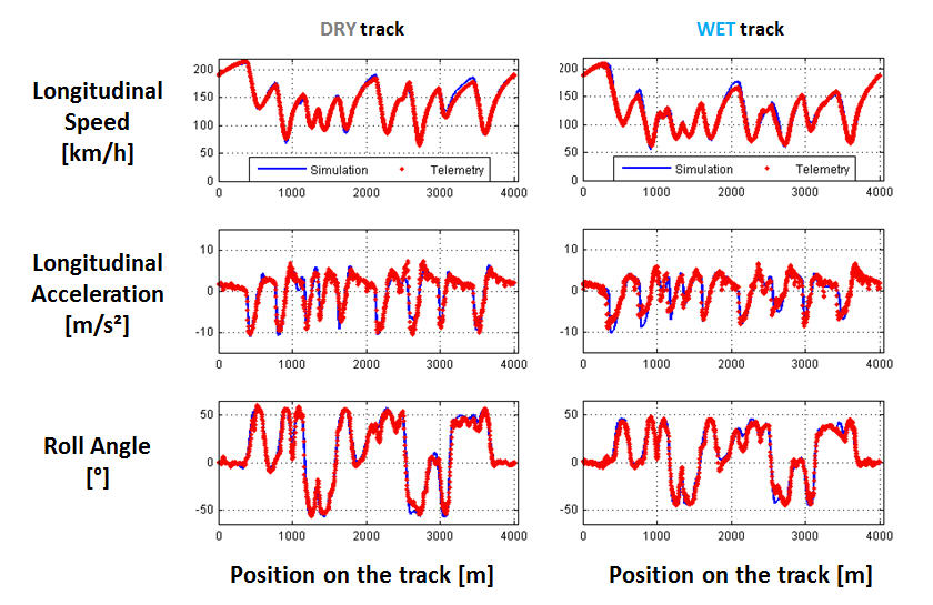
A comparison with experimental data is presented to appreciate how accurate could be this kind of simulations considering the same motorcycle and different tyre-road interaction conditions (e.g. dry and wet paved track) and thus to validate the model included in this tool. In the current example the tests are performed on the international circuit of Valencia (Comunidad Valenciana) by a professional rider using a 125cc race motorcycle.

Fig.2 Simulation results compared with experimental data for a 125cc motorcycle and Valencia circuit.
From this comparison it turns out how the accordance between simulations results and experimental evidence data is quite good and how the ideal rider of the Optimal Manoeuvre Method is capable of changing its riding style end the amount of thrust and braking forces as the conditions of the track change (e.g. adherence conditions of the road).
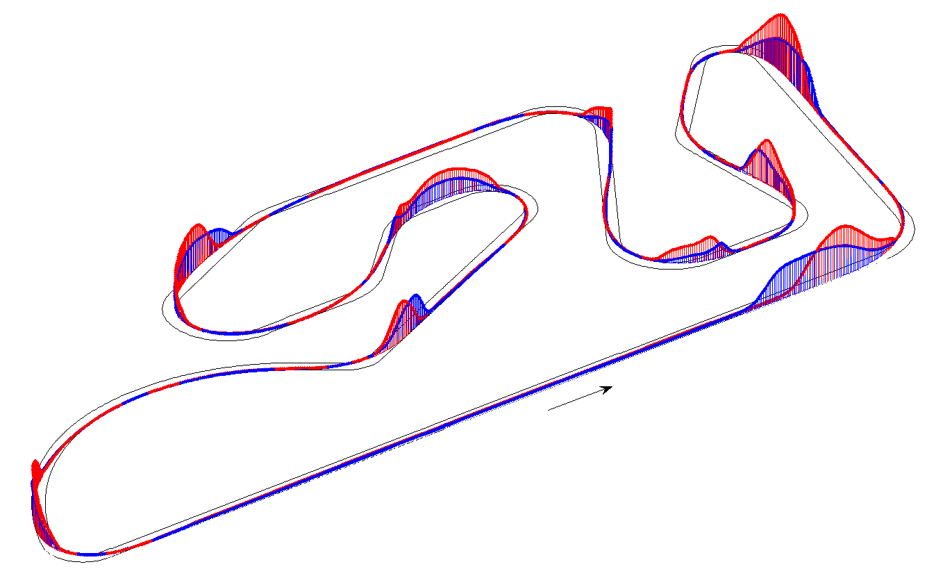
Fig.3 reports a comparison between braking forces on dry and wet track to underline the different riding strategies adopted in the two road conditions. Trajectories are optimized for the two cases and are slightly different.
One of the possible application of XOptima is to perform an optimization based on the concept of maneuverability, i.e. the ability of a vehicle to complete a given manoeuvre as fast as possible without exceeding existing physical limitations, like tyre adherence or road borders, but without considering the physical and mental pilot effort, that are concepts typical of handling. According to this, the choice of an ideal optimal rider is required.
Thus the “Optimal Maneuver Method” can be used as an advanced tool that can help engineers to optimize some relevant parameters of the vehicle geometry, without building prototypes, e.g. the optimization of the centre of mass position.
The advantages or disadvantages of the choice of a particular position of the centre of mass depend mainly on track geometry, engine power and the tyres adherence due to wet or dry ground conditions. These can change many times during the race week end.
This is the reason why it is very important for a racing team to have a starting point, optimized on the current conditions of the road, to submit to the rider during several round of testing.
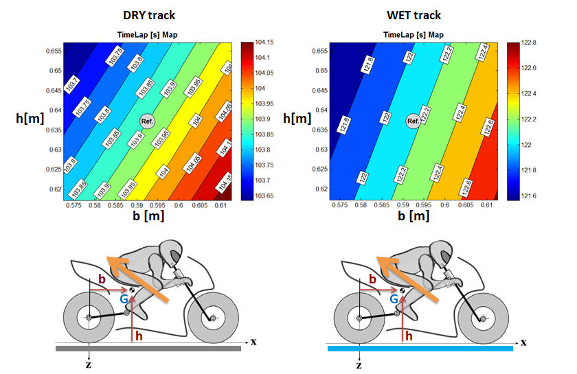
In order to perform an optimization of the position of the centre of mass of the vehicle, in both dry and wet conditions of the road, a parametric analysis has been carried out. The choice of this parameter is due to its paramount importance and to the possibility of adjusting it in real races. The height h and the lateral position b of the centre of mass have been changed. The resulting maps reporting lap times for the different configurations are presented in Fig.4.

Fig.4 Maps of the lap times due to the variation of the position of the centre of mass of the vehicle in DRY and WET conditions. From ref.1
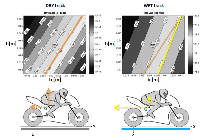
The importance of these kind of maps is not only due to the possibility of knowing which is the minimum-time settings of the bike but also to know which of the parameters has more influence in order to reach the target of the optimization, like shown in Fig.5.

Fig.5 Influence of the height and longitudinal position of the centre of mass on minimum lap time in DRY and WET track.
References:
[1]. V.Cossalter, R.Lot, D.Tavernini, Optimization of the centre of mass position of a racing motorcycle in dry and wet track by means of the “Optimal Maneuver Method””, IEEE International Conference on Mechatronics (ICM) 2013 Vicenza (Italy).

